
Our Senior Product Manager, Andrew Bryars clarifies the best practices for using equipment cooling fans, explaining the technical aspects of airflow, temperature, and the power load of appliances.
OVERVIEW
- Operating ambient temperature impacts the heat of power supplies and the end equipment assemblies within an enclosure potentially beyond their operating temperature.
- Cooling power supplies and sub-assemblies with equipment fans involves calculating the airflow required and understanding the pressure drop.
- Thermal management has a significant impact on maintaining the lifetime and reliability of power supplies and system sub-assemblies.
Everyone knows that if you dissipate heat inside a confined space or enclosure, then the temperature in that space will increase. As the ambient air temperature rises, both the power supply and the load will heat up further, possibly beyond their maximum operating temperatures.
You want to avoid a situation like this, as heat is the number one cause of unreliability and/or a reduced power supply lifetime within an electronic system. The reason for this is that the endurance of electrolytic capacitors is strongly linked to a lower operating case temperature. This is where cooling power supplies come into play.
How cooling power supplies work
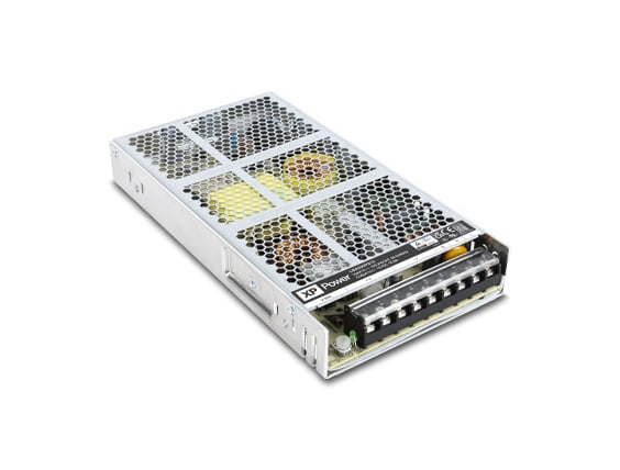
Some power supplies are designed to be force-cooled using a system fan, which removes the excess heat from the enclosure. In these cases, the airflow required for adequate cooling will be specified in the power supply data sheet. It is important to bear in mind that this is the airflow needed at the location of the power supply itself — a fan placed even a short distance away will not be sufficient.
Since air always follows the path of least resistance, only a portion of the air pushed by the fan will reach the power supply where it is needed. Internal panels for directing airflow (baffles) will help channel air along the required path to reach and cool the target components.
How to calculate airflow
Whether the equipment needs to run at a lower temperature, or the power supply requires external fan cooling the airflow needs to be calculated using the following steps:
Establish maximum temperature
Firstly, the maximum operating temperature at which either the power supply or the electronics can safely operate must be established. For the power supply itself, this may typically be 50°C and is usually related to the safety approvals or the need for a lower value to increase the lifetime of the components. A general rule of thumb is that a reduction of an electrolytic capacitor case temperature of 10°C results in a doubling of the power supply’s lifetime.
You then need to consider the highest air temperature surrounding the equipment enclosure that contains the power supply. The difference between the two will be the highest permitted temperature rise. For example, consider the power supply can operate at an ambient of 50°C. If the power supply container is meant to work in a non-air-conditioned environment — where the maximum temperature could reach as high as 40°C — the total temperature rise permitted would be 10 °C.
Determine power dissipation
The next step is to establish the amount of power that will dissipated. The total power dissipated inside the enclosure is the sum of the power used by the load, plus the power lost by the power supply as waste heat. As an example, if the load taken by the electronics is normally 260 W and assuming that the power supply is 80% efficient then the total heat dissipated is 260 W / 0.8 i.e. 325 W. Establishing the volume of airflow required can then be calculated.
There is a simple universal formula for working out how much airflow is required to maintain a particular temperature rise for a given amount of heat, which uses a constant of 2.6.
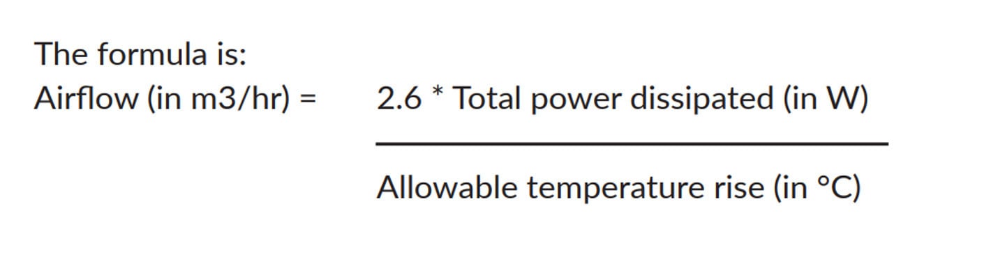
The formula is airflow (in m3/hr) = 2.6 * total power dissipated (in W) / allowable temperature rise (in °C). In our example, the airflow required would be 2.6 * 325W / 10°C = 84.5 m3/hr
How to control air flow
Unfortunately, finding a solution is not as straightforward as working out the required airflow. By using the above calculations, you should be able to choose an appropriate rating for the fan airflow, but in reality, an enclosure will have a natural resistance to air flow, otherwise known as pressure drop.
Pressure drop
The loss in pressure detracts from the fan’s free air delivery, which is the volume of air that is released throughout the device over a period of time. Drops will also vary between every application, depending on the PCB size and location, the size of inlet and outlet vents, and the cross-sectional area that the air flows through.
Where things get a little tricky is that the pressure loss also depends on the speed of the air as it passes through the enclosure. What’s more, pressure loss is in turn affected by air speed. A faster air speed will result in a higher pressure loss, but this drop reduces the air speed. If careful fan selection is not carried out, the fan could become useless. For instance, in an application where the resulting pressure loss and air speed reach an equilibrium point below the required level to remove heat from the enclosure.
It would be too complex to determine the actual pressure loss for every application, as this requires detailed knowledge of fluid dynamic equations. However, we can approximate it by using the characteristic device curve shown below in Figure 1. This will give an initial starting point that can be used for further evaluation.
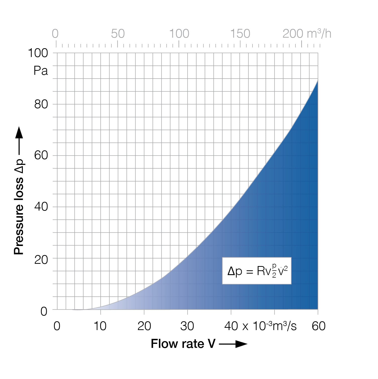
Figure 1 - Characteristic device curve
If we consider the airflow calculated previously, the curve indicates that the pressure loss would be at 11Pa. Therefore, we know that we need a fan that can generate an airflow of 84.5m3/hr into a pressure loss of 11Pa.
Each fan manufacturer will publish a graph for every fan indicating the air flow at varying pressure losses. In the example below, Figure 2, curves are given for five fans. The light coloured cone shows the optimum operating range for each of the fans. In our example, fan number five would need to be used to ensure the required airflow of 84.5m3/hr with a pressure drop of 11Pa
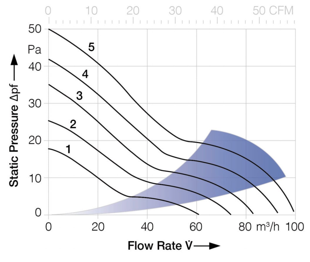
Figure 2 - Fan flow rates at different air pressures
How to manage power supply lifetime
All these factors are considered by the power supply designer before the manufacturers apply design de-rating rules to ensure that the product lifetime is adequate. These rules do not account for the mission profile, environment, mounting orientation, positioning, surrounding space, applied load, and system cooling/venting arrangements installed in the end equipment. Capacitor lifetime, particularly in convection or naturally cooled environments, should be reassessed based on the installation. How can users manage the lifetime of power supplies?
Case temperatures
Clearly, the measurement of applied ripple currents (the AC portion of the current signal) is not practical. Yet given that both the overall equipment and power supply design determine the component’s effective operating temperature, a good indication of the service life of each capacitor can be measured by taking its case temperature. and the application of the Arrhenius equation and mission profile to the base lifetime specified by the component manufacturer.
Service life
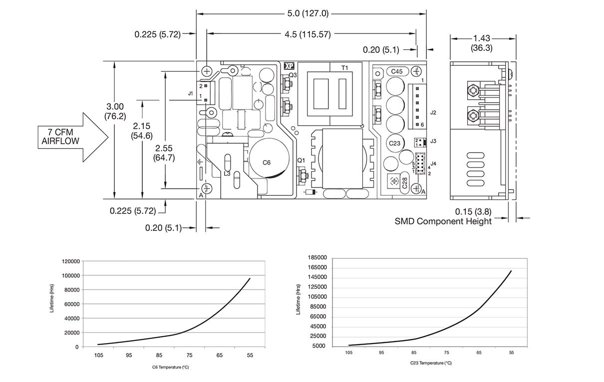
Many power supply data sheets, such as XPs GCS series, identify the key components that determine the lifetime of the product. This is particularly true for those requiring external cooling from the end equipment, and for those designed for convection cooled applications.
Recognizing these assists the system designer in determining power supply service life in the end application. The mechanical drawing below identifies the components and the curves indicate the expected service life of the power supply based on the temperature of two capacitors (C6 & C23).
Once the required pressure drop and air flow have been established, there are a few other considerations to take into account. As previously stated, for general equipment cooling, the fan can be located anywhere so long as the air flows through the heat source components.
Forced cooling
For a power supply that is designed to be force-cooled, the amount of air flowing over it is critical for correct and reliable operation. If the fan cannot be located right at the power supply, or if the entire air flow cannot be directed over it, then the fan chosen will need to have a much larger rating.
Some fans are specified with an air speed in linear feet per minute (LFM), while others have a volumetric rating in cubic feet per minute (CFM) or cubic meters per hour (m3/hr). To convert between the two, the cross-sectional area of the fan vent system needs to be known — this is the only reliable way to do so. For a force-cooled power supply, the required air flow may be given in either a speed rating such as LFM or a volumetric rating such as CFM.
Dust filters
Equipment with fans often have filters to prevent the entry of unwanted dust. These will add to the resistance of air flow, contributing to pressure loss, so will need to be taken into consideration. More importantly, as the filter clogs with dirt, the pressure loss may grow significantly higher, and a fan with a suitable rating at the beginning of operation could become the wrong choice after some use. For this reason, dust filters should be regularly cleaned or replaced.
How to minimize noise
Adding a fan to a piece of equipment makes it audibly noisy. Some applications cannot tolerate any noise — such as in hospitals or recording studios. Even for uses in a loud environment, it is usually desirable to minimize interferences like this. This can be done by several methods.
Fan bearings
One way to minimize noise is by using a fan with a higher quality bearing. Ball bearing fans, which use a ring of balls around the shaft to solve uneven wear and rotor wobble problems, are generally quieter than sleeve bearing fans (encased in their titular sleeve-like structure) and have the advantage of a longer lifetime. Of course, there are fans that use impregnated oil within sleeve bearings that may counteract this.
Blade speed
Also, for a given air volume, a larger fan is generally quieter than a smaller fan due to the slower blade speed required. Consideration should also be given to any noise generated by fan blades passing by a nearby fixed part of the fan such as a strut or a finger guard. If a finger guard can be separated even slightly from the fan blades, then the sound may be reduced.
Another method to minimize this type of disturbance is to reduce the fan supply voltage. Fans are specified with an operating voltage range and those with a DC input usually spin at a speed dependent upon the actual DC voltage supplied. The slower the spinning fan, the less audible it will be.
How to use data to manage temperature
Thermal management of modern power supplies is becoming increasingly important due to higher power densities and smaller volumes of heat sinks. Due to this, data sheets now contain information essential for equipment designers. This ensures that the power supplies are not operated at too high a temperature in the form of specific maximum temperatures for a selection of components.
Once the fan has been chosen using this method, a final check should be conducted by measuring these component temperatures in the final configuration. If it looks like the component temperature will exceed the value indicated in the data sheet, then the airflow and direction should be re-assessed.
Please feel free to contact us for more information regarding the proper cooling of power supplies.

Andrew Bryars
Andrew Bryars graduated with an Honors Degree in Electrical and Electronic Engineering and has worked in the power supply industry since 1990. He has been with XP for over 25 years and has held a variety of engineering, sales, and management jobs culminating in his present position as Senior Product Manager.