Our Product Marketing Manager, Shravan Govindaraj, sheds light on patient leakage current in medical power supplies and offers insight on how to control it in demanding medical applications.
Overview
Learn how IEC 60601 standards are pivotal for governing medical electrical equipment.
Explore the diverse types of leakage currents and understand their significance in medical applications.
Find out how custom power supply design and modification can reduce leakage current and enhance patient safety.
IEC 60601 compliance and leakage current limits
In the world of medical electrical equipment, compliance with the IEC 60601 standard is crucial for ensuring patient safety. This standard sets limits on leakage currents, especially for parts of the equipment that touch the patient during regular use.
These parts are Type B (body), BF (body floating), Type CF (cardiac floating) with Type B being the least strict. Type B applied parts may be connected to earth, while Type BF and CF are 'floating' and must be separated from earth. Type BF parts have conductive contact with the patient, or medium to long-term contact with the patient, like ultrasound equipment and blood pressure monitors. Type CF parts have the most stringent classification as they are parts that may come into direct contact with the heart like dialysis machines.
What is patient leakage current?
Leakage currents are classified into three types: earth leakage current, enclosure leakage current and applied part/patient leakage, each with its specified limit. Patient leakage current is usually the toughest to meet. It's the current that unintentionally flows from the equipment, through the patient, and to the ground due to an external voltage source.
New limits and factors in managing patient leakage current
For the third edition of the standard, the limit is 100uA for B and BF, and just 10uA for CF. In power supplies, patient leakage current is defined as the current leaking from the output through a 1 kΩ impedance to the ground, which represents the patient.
The patient leakage current is directly proportional to the capacitance between the power source and the device's output. This capacitance is influenced by the transformer's design and the Y-capacitors bridging the primary side to the secondary side. We aim to minimize this capacitance, but complete removal isn't an option due to safety standards.
Reducing the input-to-output capacitance of a medical power supply
Let's consider the input-to-output capacitance of a typical medical power supply. Figure 1 below is a simple representation of such a device. In the absence of any bridging capacitors, the dominant path for the patient leakage current is through the transformer (marked by dotted line).
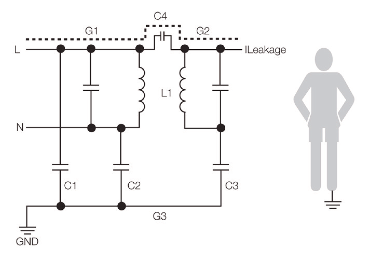
Figure 1
The capacitance between the primary side and the secondary side of the transformer comprises the bridging capacitance (C4) and the transformer’s interwinding capacitance. If C4 increases, the impedance of this current path decreases; if the impedance decreases, more current will flow through point G2.
This current constitutes the patient leakage current. Note that C1 and C3 also create a path for current leakage – this is the earth leakage current rather than the patient leakage current.
Figure 2 below is a capacitance model of Figure 1. The patient leakage current, Ileakage, is calculated as 2.π.f.C4.Vmains. That is, the patient leakage current is directly proportional to the bridging capacitance.
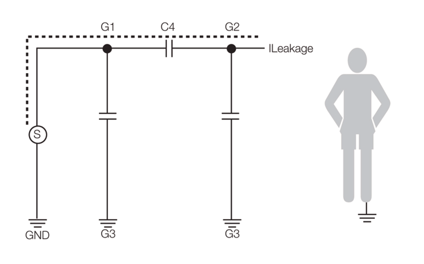
Figure 2
Popular techniques for reducing the patient leakage current, therefore, focus on reducing the input-to-output capacitance of the power supply. Probably the most common method of doing this is to add an additional DC-DC converter between the power supply and the applied part. This adds an extra layer of isolation as shown in Figure 3 below.
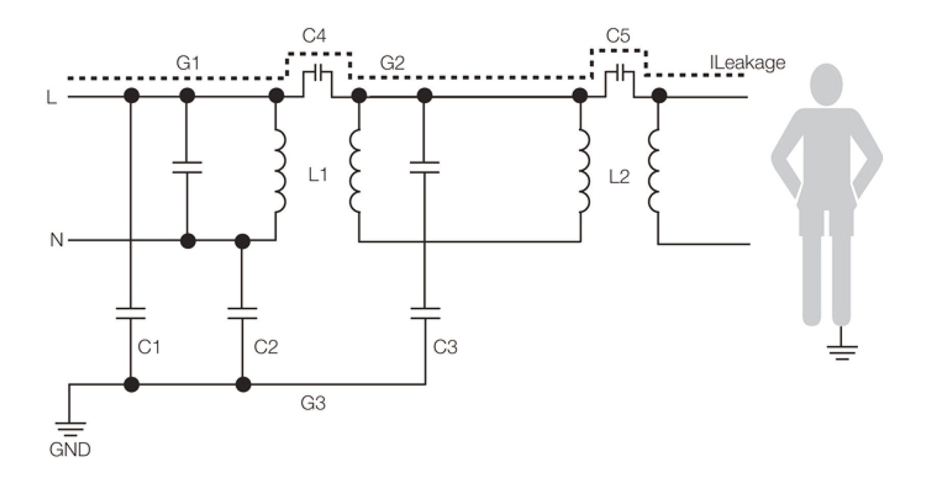
Figure 3
The dominant path for the current of the new system is now through C4 and C5 – the interwinding capacitances of both transformers. The new patient leakage current is calculated as ILeakage = 2.π.f.C4 and C5 in series.
Vmains (as shown in the capacitance model in Figure 4 below) is greatly reduced overall to acceptable levels.
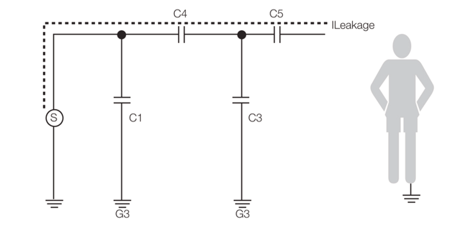
Figure 4
How DC-DC converters enhance leakage current control
As an example, recent work on a customer’s medical system by XP Power reduced a medical AC-DC power supply’s patient leakage current from 11μA to 6μA by adding an additional DC-DC converter as described above.
Although this is an easy way to reduce the output capacitance, and therefore the patient leakage current, it does have its downsides. Adding another DC-DC converter to the system is always going to add cost and complexity, as well as increase the footprint of the power subsystem.
Customizing power supplies for patient safety
An alternative approach is to work with XP Power to modify standard medical power supplies to meet the requirements. This involves optimizing components like shielding in the transformer and reducing Y capacitors.
We have successfully modified standard medical power supplies to meet BF/CF leakage current requirements, with patient leakage currents below 10uA. These modifications can be based on XP Power’s GCS or ECM60 series, which meet isolation requirements and come in compact footprints.
Summary
Meeting stringent patient safety standards for medical power supplies is a priority, with patient leakage current often posing the biggest challenge. Solutions involve reducing input-to-output capacitance, which can be complex due to EMI concerns.
While adding a DC-DC converter is an option, XP Power's approach of modifying standard power supplies might be a more cost-effective choice for your medical application.
Please feel free to contact us for more information regarding our trusted, safe solutions for your medical power challenges.

