
In harsh environments where a sealed enclosure is necessary, baseplate cooling is a simple and inexpensive solution to thermal management of power supplies, says Peter Blyth, XP Power. A new approach using discrete components can make baseplate cooled power supplies smaller, more efficient and more flexible.
Demand for power supplies that can withstand harsh environmental conditions doesn’t only come from the military. Telecommunications base stations and infrastructure for the smart electricity grid of the future place steep demands on their power supplies. These systems are subject to the extremes of temperature, dust and humidity. The equipment needs to operate continuously, as well as reliably, since performing maintenance at remote locations can be difficult and downtime is unacceptable. Sealed enclosures to prevent dust and moisture ingress are often used to protect the system from its environment, but this poses a problem for thermal management of power supplies.
A common power supply cooling solution for inside a sealed box is to use a small convection cooled power supply and over-rate it. For example, if you take a power supply that is rated for full power at 50°C ambient temperature, it might derate by 50% at 70°C. So for operation at the elevated temperature, a power supply rated for twice the actual output would be needed. This works up to a point, but for the high power levels that are required for smart grid infrastructure or a telecoms base station, it’s not feasible – in this example, a system that requires 500W would need a 1000W convection cooled power supply, which is not practical from a size and cost point of view.
If high power requirements have ruled out convection cooling, a way of getting heat out of the box must be considered. Sealed enclosures prohibit forced air cooling as fans can suck in dirt and dust. Filtering is possible but this cuts down the air flow significantly, meaning a larger fan is needed, and they are susceptible to blockages. This obviously affects the reliability and maintenance demands of the system. An alternative solution is therefore required to get the heat from the power supply out of the box; using a baseplate cooled unit is a simple and inexpensive way of doing this.
Baseplate basics
A baseplate cooled power supply has most of its heat generating components, such as the switching FETs, diodes and magnetics, mounted in direct contact with the metal baseplate so that heat can be extracted using thermal conduction (Figure 1).

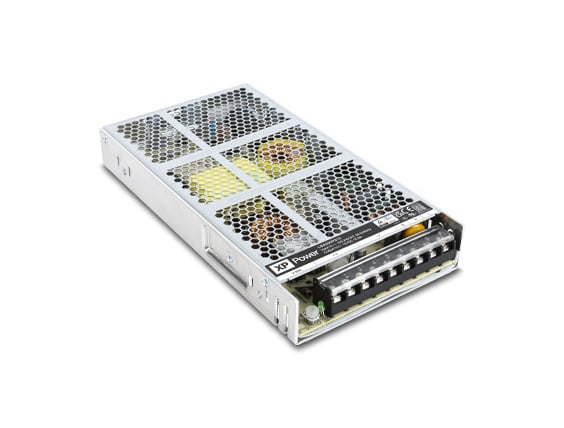
Figure 1. The CCH series of 400W and 600W power supplies from XP features a 6mm baseplate.
Typically the power supply is then bolted to the inside of the sealed box, so that the metal box itself can act as a heat sink, or heat can be transferred from the box to an additional externally mounted heat sink. It’s wise to check whether the box can act as a large enough heat sink to conduct the heat out of the unit, or whether an additional external heat sink should be added, because getting this wrong will have a significant impact on the reliability of the power supply.
For example, let’s consider the CCH series baseplate cooled power supply from XP Power, which has a maximum baseplate temperature of 85 °C operating in an ambient air temperature of 40 °C (figure 2).

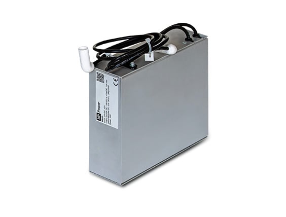
Figure 2. Mounting a CCH power supply on the inside of a metal enclosure.
The thermal resistance required can be calculated to determine whether an additional external heat sink is required.
Operating at 400 W, this power supply is 90% efficient (Figure 3).

Figure 3. In our example, the efficiency of the CCH power supply is 90% at 400W output.
Efficiency = Power out / Power in, so therefore: Power out / Power in = 0.9
We know the Power out of the system is 400 W, so: Power in = 400/0.9 = 444.5W.
444.5 - 400 = 44.5 W is therefore dissipated (wasted) as heat.
Assuming a perfect thermal impedance between the baseplate and heatsink, we can use the following formula, where Tbaseplate and Tambient are the baseplate and ambient temperatures and θba is the thermal resistance between the baseplate and the ambient air:
Tbaseplate = Tambient + (θba x Power dissipated)
θba = (85-40)°C / 44.5 W = 1.0°C/W
From this calculation, we can deduce that a heatsink with a thermal impedance of 1.0°C/W or less is required to maintain the baseplate temperature at 85°C or below.
Be warned that this is only a basic check, though – heat sink design is a complex process. Once the calculations have been done, tests should be run to check the temperatures of key components, such as the baseplate and capacitors to ensure everything is cooling sufficiently as intended.
Power supply design success
The design of the power supply unit itself can also have a significant impact on the success of baseplate cooled designs. Obviously, it helps if the power supply is as efficient as possible, and as waste heat generated is directly proportional to the efficiency, higher efficiency means a smaller heat sink can be used. Looking at it the other way around, if you kept the same heat sink and increased the efficiency of the power supply, the temperature inside the case would be lower, which would increase the expected lifetime of the power supply (as a rough yardstick, reducing ambient temperature by 10°C doubles the lifetime of a capacitor in a power supply). Temperature inside the case is the main contributor to the lifetime of a power supply, so this is especially attractive.
Traditional baseplate cooled power supply designs use third party power modules. These dc-dc modules, although designed for baseplate cooling, often require external components for filter compliance and power factor correction, and it can be challenging to place these parts for optimum EMC compliance and cooling. While the modules themselves have high efficiency, the overall efficiency can be affected by these extra filter components and the discrete PFC stage.
Using discrete components instead of relying on modules, like in the CCH series, can alleviate this by allowing the efficiency of each stage to be optimised. All the key heat generating components to be placed with optimum circuit flow next to the baseplate, and components that are heat sensitive, like the reservoir capacitor, to be placed away from it or even insulated from the (hot) baseplate to extend its life. Heat generating components can also be spaced as evenly as possible around the baseplate to make heat transfer more efficient by avoiding hot spots.
Designed with noise requirements and EMC compliance in mind
Having the IP of the whole circuit means more flexibility is available. That is, it allows the manufacturer to cater for the many modified standard requests which are thrown up by the diversity of applications. It also means that the power supply can be designed with noise requirements and EMC compliance in mind from the start - protection from mains-borne transients can be added at the front end to make the design extremely robust. As an example, the discretely implemented CCH series meets industrial standard EN55022 Class B as well as MIL-STD-461 with ease. MIL-STD-461 for conducted noise covers frequencies down to 10kHz, which even with an inherently low power module would require external capacitors to maintain.
A final argument for an entirely discrete implementation in a baseplate cooled power supply is that third party modules are bound to the size of that module; in a discrete design the full volume can be utilised by optimising the physical layout of the components.
In summary, for applications like smart grid infrastructure or telecoms base stations, baseplate cooled designs are a simple and efficient way of keeping power supplies cool. Advances in baseplate cooled power supplies using discrete components can offer more efficient heat transfer, effortless meeting of noise rules and compact design.
These PSUs are designed from the ground up for the special conditions imposed by harsh environments and can be more easily tweaked to meet individual applications’ requirements.

Peter Blyth
Peter has worked for XP Power since June 1997. His career started as an applications engineer, then moved into sales in 1998. In 2002 he relocated to the USA as the Medical Sales Director, based out of XP Power's Orange County design office, returning to the UK in July 2009. He took up the post of Global Medical Industry Director and then in 2011 was promoted to Executive Vice President - European Sales.