
AC input current and harmonics
Our applications engineer, Kent Smith, looks at why managing harmonic currents in your PSU is crucial to ensure the quality and reliability of electrical power distribution and discusses how to avoid issues such as voltage distortion, power inefficiency and equipment damage.
Overview:
- Harmonic current generation in power supplies and the impact on power quality
- Legislation and equipment classes for harmonic emission limits
- Solutions for mitigating harmonic distortion
- The advantages and disadvantages of passive and active power factor correction in PSUs
As a result of the peak rectification techniques used in power supplies, harmonic currents are generated. To limit these harmonics, EN 61000-3-2 is used for equipment with an input current ≤16 A per phase.
Harmonic limits and power supply requirements by equipment class
EN61000-3-2 established four classes of equipment, each with their own limits for harmonic emissions:
- Class D - T.V.s, personal computers and monitors consuming
- Class C - Lighting equipment
- Class B - Portable tools
- Class A - Everything else
Equipment Classes A and B have absolute limits for harmonics whatever the input power. Class C equipment has limits expressed as a percentage of the 50 Hz current consumed. Class D equipment has limits that are proportional to the mains power consumed. Equipment categorized in Classes C and D will normally require a power supply incorporating active power factor correction.
Rectification process and bulk capacitor operation
In the diagram below, the incoming AC voltage wave form is identified as VLINE. The dotted line represents the rectified AC voltage following the bridge rectifier.
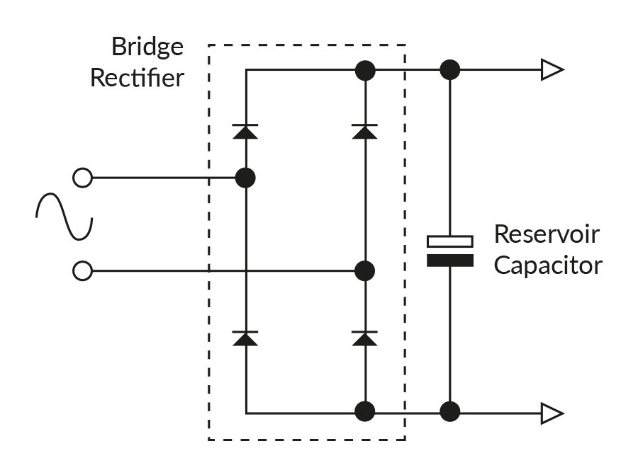
Figure 1
The bulk capacitor is charged during the conduction angle and is discharged slowly by the power stage of the power supply (VCAP). As soon as the input sine wave voltage falls below the bulk capacitor voltage, the diode in the bridge rectifier is reverse biased and no current flows until the incoming rectified sine wave is once again higher than the bulk capacitor voltage. The conduction angle is typically 2-3 ms.
The complex input current waveform generates the harmonics which are of concern to the power generator. The harmonics contribute to the apparent power (real power and apparent power are discussed later in more detail). The current waveform shown will result in a power factor of around 0.5 - 0.6.
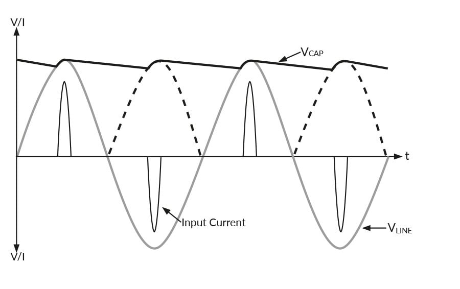 Figure 2
Why is harmonic distortion a problem?
The utility provider must supply the voltage and all of the current, even though some of the current is not turned into useful output power. The provider has no means of charging for the extra current because the power is charged in kWh.
The combined effect of millions of power supplies is to clip the AC voltage because all of the current is drawn at the peak of the sine wave. Power conductors must be sized to carry the extra current caused by the low power factor. Neutral conductors can overheat because they are typically not sized to carry all of the harmonic currents which do not exist for high power factor loads.
What is passive power factor correction?
To meet the legislation for harmonic distortion there are two main solutions available for power supplies. We’ll deal with passive power factor correction first which typically involves the addition of a line frequency inductor or resistor into the AC line. The effect of the inductor is to squash the current wave shape as the inductor is a reactive component which resists change in current. The effect of the resistor is to reduce the peak current. The smoother the current wave-shape the less harmonic distortion will be present.
 Figure 3
When is passive power factor correction suitable?
Passive power factor correction is a very simple solution, but you should be aware of its advantages and disadvantages. It is not practical in power supplies above 300 W due to the size of the components required to provide adequate inductance at 50/60 Hz and to keep the resistive losses low enough. This solution is not adequate in lighting, personal computing or colour television applications, but is a viable solution for Class A equipment. Figure 4 below shows real time measurement of passive power factor correction and the harmonic current levels.
 Figure 4
Active power factor correction
The second solution to look at is active power factor correction. This uses a boost converter running at high frequency to electronically control the wave-shape of the input current. The incoming AC voltage is monitored and used as a reference to determine the pulse width of each current pulse of the high frequency switched current.
The current is drawn in a series of pulses at around 100 kHz which equates to 2000 pulses per cycle of the mains voltage.
 Figure 5
The low pass EMC filter takes the high frequency element and filters it out so that the current seen by the mains supply is sinusoidal. The system regulates the DC output at approximately 400 VDC. The diagram below shows real time measurement of active power factor correction.
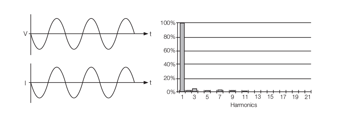 Figure 6
Comparing passive and active power factor correction
Passive power factor correction offers simplicity and reliability while assisting in reducing noise (EMI) and helping with filtering. However, it comes with disadvantages such as the need for heavy and bulky components, AC range switching, and a tendency for lower power factor. These factors and others can limit the use of multiple PSUs within a system.
On the other hand, active power factor correction provides a high power factor (>0.9), low input current, and compatibility with universal inputs. It also ensures a regulated high voltage bus, a hold-up time that is less dependent on the input voltage, and the ability to use multiple PSUs. However, it comes with higher costs, increased complexity, a larger component count, and a potentially lower calculated Mean Time Between Failures (MTBF).
Summary
Managing harmonic currents in power supplies is essential to ensure compliance with regulations, maintain power quality and improve energy efficiency. Additionally, you can reduce EMI-related issues, extend your equipment lifespan and control your operational costs.
Please contact a member of our dedicated support team for further information regarding our market leading power solutions.

Kent Smith
Kent is a Regional Applications Engineer with XP Power covering eastern North America. He's been with XP Power for over 14 years and previously was a design engineer with a company in the test equipment market. Kent graduated with a Mechanical Engineering degree from Rensselaer Polytechnic Institute.