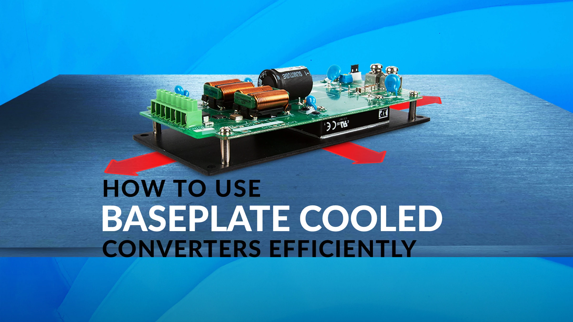
Our Senior Product Manager shares information on how baseplate cooled low voltage converter modules can be used efficiently.
OVERVIEW
- Baseplate cooled converter modules are power solutions that are ideal for harsh environments & outdoor use.
- Baseplate cooled converters are component-level power solutions rather than drop-in products.
- Thermal management is a key element in the integration of power bricks which are designed to be baseplate cooled.
Baseplate cooled modules require additional external components for correct operation, reverse polarity protection, control of noise emissions, and protection against spikes and surges.
When designing electrical equipment for outdoor use or harsh environments, there are several design challenges that need to be overcome. Firstly, the equipment needs to be sealed from external environmental conditions, and second, a reliable power supply will be required.
Most high-power supplies use forced air cooling to dissipate the heat generated, but this approach is not practical in a completely sealed unit. That’s why baseplate cooled converter modules have become a popular solution for these applications.
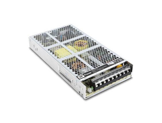
What are baseplate cooled converter modules?
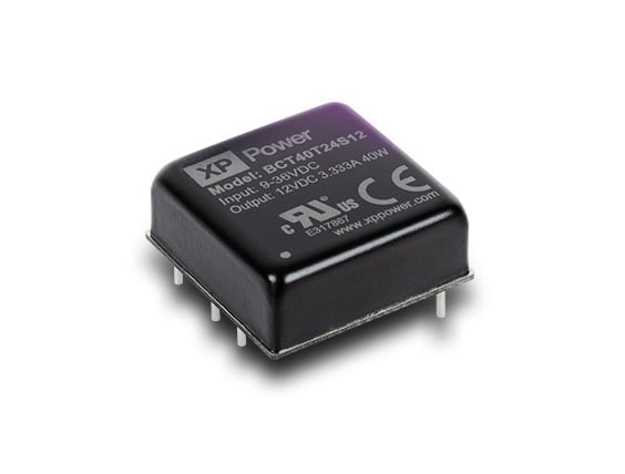
Baseplate cooled power converter modules, also known as bricks, provide building block power solutions for integration into end equipment. These high-density power solutions are ideal for rugged outdoor sealed enclosures, transportation, and defense applications, where their rugged construction and conduction-cooled properties are beneficial. They’re also well suited to high-density forced air-cooled applications where the benefits of the compact size can be realized.
They also provide the building blocks for low-risk bespoke power solutions designed either by the end equipment designer using support and application notes from the manufacturer or by the module manufacturer itself using the proven, reliable module as a base for low development cost, low-risk custom solutions with accelerated time to market.
Which applications are baseplate cooled converters compatible with?
Baseplate cooled converters are component-level power solutions rather than drop-in products, which generally require additional design resources and components for correct operation, electrical safety, thermal management, and electro-magnetic compatibility (EMC). They are designed for both DC and AC input applications, with input ranges designed to cover battery and DC vehicle supplies as well as higher voltage, rectified or power factor corrected (PFC) AC supplies.
The industry has developed standard sizes for these parts, described as eighth bricks, quarter bricks, half bricks, and full bricks. Power ratings up to 600 or 700 W can be achieved in a standard 2:1 input full brick, though power density reduces as the input range is widened to 4:1, 8:1, or even 12:1 to accommodate multiple nominal battery supplies in a drive to standardize system design for multiple power platforms.
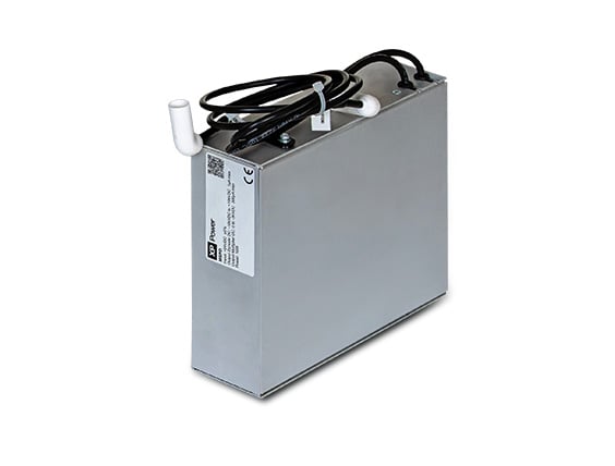
Baseplate cooled converters with AC input are also available either as a more complete solution providing AC to low-voltage DC conversion or as PFC modules with high-voltage outputs (usually around 400 VDC) to drive downstream high input voltage DC-DC bricks. Most of these AC input products also require additional design and components, including high-voltage electrolytic capacitors and components for EMC, with one or two exceptions such as the ASB series of 75, 110 & 160W complete AC-DC full-brick solutions from XP Power, which only require thermal management and include all other parts.
The key elements of power brick integration
Thermal management
Thermal management is a key element in the integration of power bricks which are designed to be baseplate cooled. The brick is designed so that the power-dissipating components, such as the power semiconductors and transformer, are thermally bonded to the baseplate, which must then be maintained below a maximum operating temperature under the worst-case conditions of the end application.
The thermal resistance of the cooling scheme must be matched to the power required by the load or end equipment and the efficiency of the module, which determines the power dissipated in the brick converter, and the maximum temperature at which the equipment is expected to operate.
The power dissipated (in Watts) can be determined from the module efficiency specification under the worst-case operating conditions, though it is important to consider the actual operating load and lowest input voltage applied rather than the datasheet headline efficiency.

Figure 1: An example of the variation in efficiency with input voltage and load
Once the efficiency at the worst-case operating point is established, the waste power to be dissipated as heat is calculated as below:
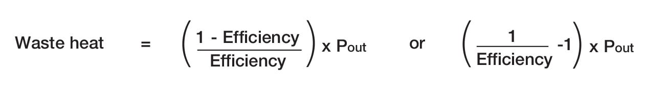
Figure 2: Calculation of waste power to be dissipated as heat]
Having determined the waste heat/power, the simple model below determines the thermal resistance required for operation, with ∆T defined as the difference between the maximum operating temperature of the equipment and the maximum baseplate temperature of the power brick. The thermal resistance from the case to heatsink is typically 0.1 ⁰C/W when using a thermal pad or grease.
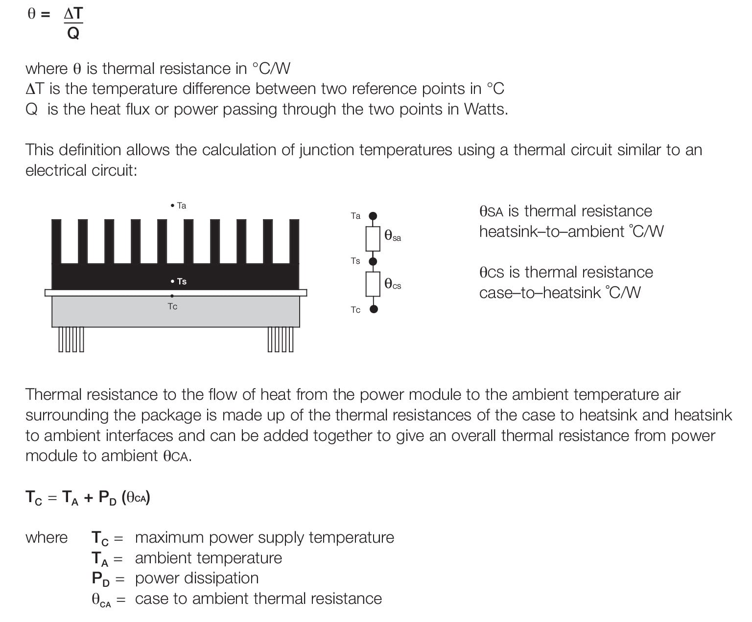
Figure 3: Power Brick and Heatsink Thermal Model
The thermal resistance of the heatsink to ambient is heavily dependent on available airflow, meaning that in convection cooled applications its physical size will be far greater than in a comparable power system with forced air or liquid cooling. When using multiple bricks connected to a common heatsink or cold wall, the sum of the dissipated power from each brick in the system under worst-case conditions determines the overall thermal resistance required.
Electro-magnetic compatibility
In addition to the thermal management outlined above, baseplate cooled modules require additional external components for correct operation, reverse polarity protection, and control of noise emissions, as well as for protection against spikes and surges defined in the susceptibility requirements of the application. This means that a network of capacitors for noise mitigation & reduction of source impedance, inductors, and surge-suppressing components must be installed within the end application. Fusing must also be implemented for safety in the event of catastrophic failure short-circuiting the supply.
The power module data sheet and application notes will specify the values of the components required, though it is up to the design engineer to implement them, following good design practices for any creepage and clearance requirements, and minimizing parasitic inductance for EMC compliance.
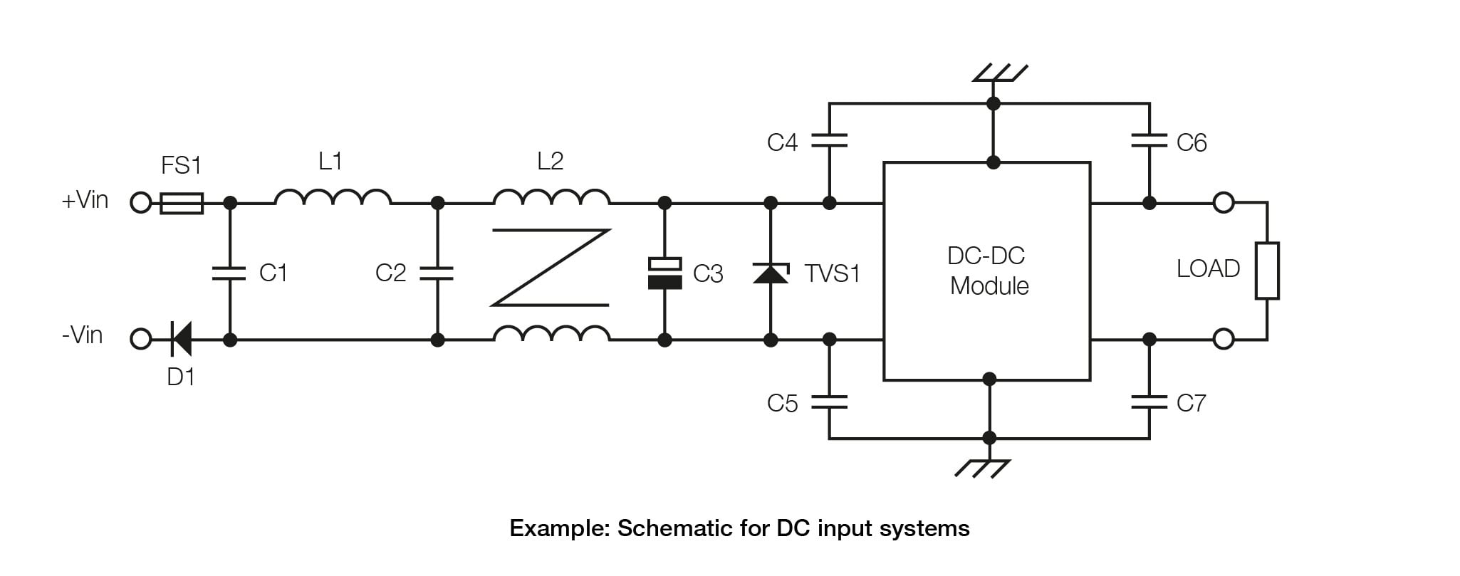
Figure 4: Schematic for DC input systems
FS1 provides protection against an input short-circuit failure, and D1 provides reverse polarity protection. L1, C1, and C2 form a pi filter to mitigate differential noise created by rapid changes in current in the power switching stage, and L2, C4, and C5 form a common mode filter to mitigate noise created by the rapid changes in voltage in the power stage. C3 presents a low impedance source for the power converter switching current demand, and TVS1 is a bi-directional transient surge suppressor to protect against spikes and surges. C6 and C7 reduce output common mode noise, and an additional differential filter may be added at the output for applications that require very low noise.
In general, the decoupling capacitors (C4, C5, C6, and C7) should be as close as possible to the pins and chassis connection to the baseplate to keep the loop as short as possible. The input electrolytic capacitor (C3) and transient voltage suppressor (TVS1) should be physically close to the input pins of the module with the loop as small as possible, and tracks beneath the power module should be avoided.
There are a limited number of application-specific filter modules available for the abnormal surges found in DC input transportation and defense applications. These generally also require a few additional components for full compliance.
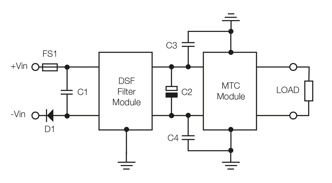
Figure 5: Schematic for DC input defense application
In this case, the DSF filter module contains all the necessary active surge protection circuits to comply with the requirements of a 28 V nominal military vehicle supply and the filter inductors. C1 completes the differential filter stage, and C3 and C4 the common mode filter stage. C2 provides a low impedance source for the MTC series DC/DC converter.
When using a PFC module solution for an AC input power system, similar EMC components are required, and a high-voltage (450 VDC) electrolytic bulk capacitor (C6) is also required, as shown. The value of the bulk capacitor is determined by the system hold-up or ride-through requirements.
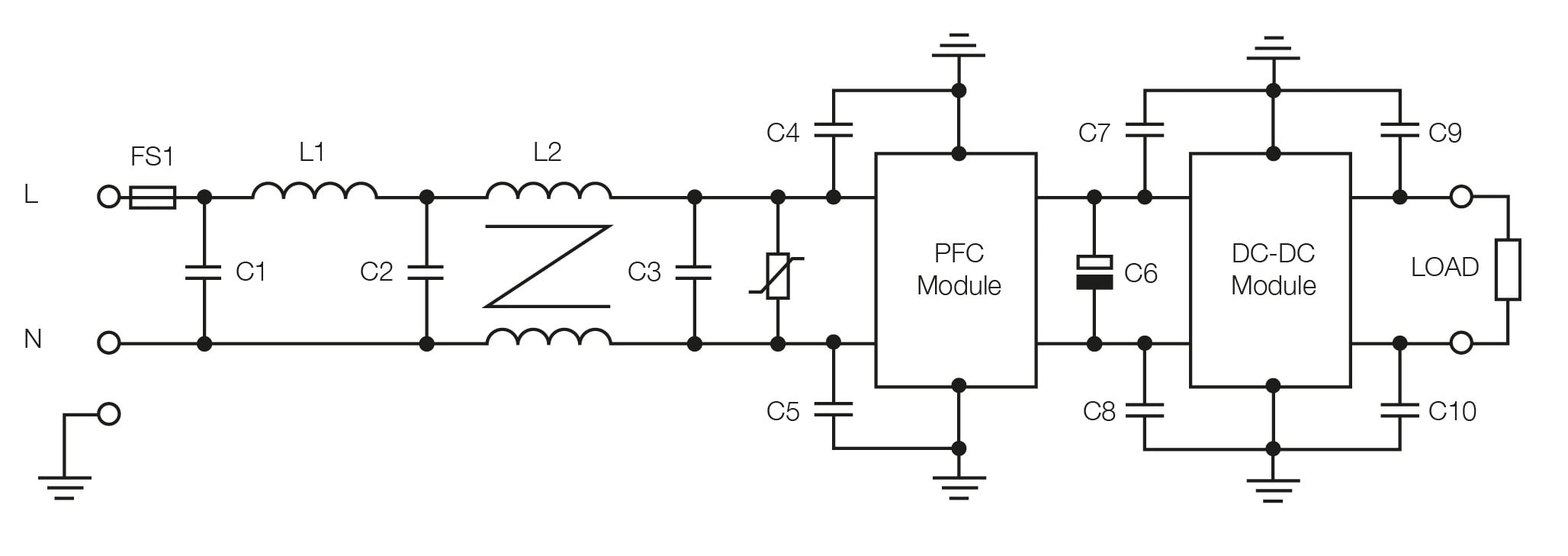
Figure 6: Schematic for AC input systems
AC input solutions
Some AC input solutions combine the PFC and DC-DC sections into one brick, with connections made available for the bulk capacitor. There are additional requirements for AC input systems regarding creepage and clearance distances between line and neutral, and between line and neutral and earth, which must be adhered to during the power system implementation. These creepage and clearance distances are outlined in the relevant safety standard for the end application.
The additional components outlined above also need careful selection and thermal management to stay within the thermal safety limits for inductors and filter capacitors, and to ensure that the electrolytic capacitors employed have the desired service life over the mission profile of the end equipment. It is possible to conduct heat away from the inductors to the equipment cold wall using suitable insulating thermal pads, and other components are often mounted on the reverse side of the PCB and kept away from any higher-temperature parts.
The best manufacturers of these high-density baseplate cooled brick converters have application information and EMC data to support design-in. There are also experienced applications engineers on hand to support the user during the design and compliance testing phases, and offer pre-compliance testing against common industrial, communications, transportation, and defense EMC standards.
The manufacturer will also have used the modules in a myriad of application-specific custom designs and gained invaluable experience in their application and compliance with safety and EMC standards.
Using the module manufacturer to design and produce a bespoke brick-based power system remains a popular choice, negating the need for the additional design and testing resources in house, and allowing the OEM to focus on the core system design.
Please feel free to contact us for more information regarding the integration of low voltage converter modules.

Andrew Bryars
Andrew Bryars graduated with an Honors Degree in Electrical and Electronic Engineering and has worked in the power supply industry since 1990. He has been with XP for over 25 years and has held a variety of engineering, sales, and management jobs culminating in his present position as Senior Product Manager.