Manufacturers’ lifetime ratings are important, but so is the specific application.
Overview:
The electrolytic capacitors in AC-DC power supplies have a finite lifetime.
Manufacturers provide an assessment of their likely durability to help buyers choose the most appropriate solution.
Other variables in different applications will also affect lifetime.
Our Technical Director, Gary Bocock summarises the manufacturer calculations and recommends an extra in-application check.
Electrolytic capacitors are an essential component of AC-DC power supplies. They provide high Capacitance x Voltage (CV) and low Equivalent Series Resistance (ESR) in low-volume packages. There’s no alternative part that can do the job cost-effectively.
Determine the service life of the power supply
The service life of these electrolytic capacitors is an increasingly key design parameter in power supplies. Power density demands are increasing, and electrolytic capacitors are the only component in the power supply that wears out. So, the type of electrolytic capacitor used in the design determines the service life of the power supply. It also dictates the service life or service interval of the end application in maintained equipment.
The topology and applied ripple current, design layout, capacitor design lifetime, capacitor temperature rating, and local heating effect vary from one product to another. They may also change under low- and high-line input conditions.
External heating effects can outweigh internal heating effects, especially in today’s increasingly compact designs. Actual service life is also dependent on the temperature rises that may take place when the power supply is installed in the application. The mission profile of the end equipment is another factor, defining average operating temperature over the equipment lifetime and usage hours per day.
Electrolytic capacitor designers take into account all these factors when defining the lifetime of their products. Let’s take a look at the calculations they work with.
Design lifetime at rated temperature
Manufacturers of electrolytic capacitors specify the design lifetime at the maximum rated ambient temperature, usually 105°C. This design lifetime can vary from as little as 1,000 hours to 10,000 hours or more. The longer the design lifetime, the longer the component will last in a given application and ambient temperature.
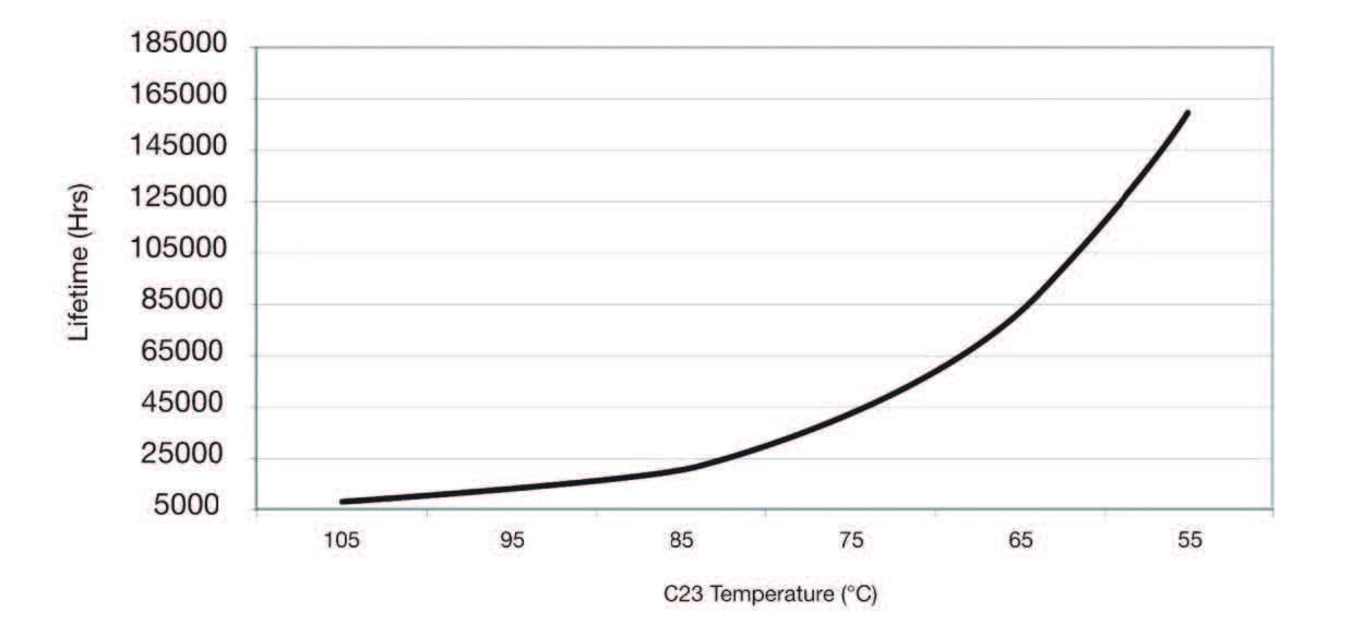
Manufacturers provide calculations to determine lifetime in application. These are based on the Arrhenius equation for temperature dependence of reaction rates. This determines that the reaction rate doubles for every 10°C rise in temperature. That means that the lifetime doubles for each 10°C reduction in temperature, so a capacitor rated at 5,000 hours at 105°C would have a service life of 10,000 hours at 95°C and 20,000 hours at 85°C.
The basic equation is given below. The curve plots the service life against ambient temperature.
Applied Ripple Current and Frequency of Operation
As well as ambient temperature and local heating effects, applied ripple currents further heat the capacitor core. Switching and rectification processes on the input and output stages of the supply generate ripple currents. These cause power dissipation within the electrolytic capacitor.
The magnitude and frequency of these ripple currents depend on the topology designed into active Power Factor Correction (PFC), where used. They also depend on the main converter power stage, both of these vary from design to design. The power dissipated within the capacitor is determined by the RMS ripple current and the capacitor ESR at the applied frequency.
The temperature rise at the component core relates to the power dissipated, the radiation factor of the component package, and the temperature difference factor or slope from the core to the case. These values are determined by the component manufacturer.
The maximum ripple current that may be applied to the capacitor is usually specified at maximum ambient temperature and 100/120 Hz. Multiplication factors can be applied, depending on the ambient temperature in actual use and the frequency of the applied ripple current: ESR decreases as frequency increases.
The Advantage of Cooling Systems
Enclosed power supplies incorporating their own cooling fans are less susceptible to the end application environment if correctly deployed. The ambient temperature must remain within specification and there must be adequate clearance for cooling.
The table below indicates the estimated service life of capacitors with design lifetimes of 2,000 and 5,000 hours at various temperatures. It assumes 24/7 operation when converting the service hours to service years. Equipment with a less intense mission profile – such as eight to ten hours per day, running five days per week – would experience significantly longer service life.
Other variables may affect longevity in power applications
Power supply manufacturers apply design de-rating rules to ensure that product lifetime is adequate.
But these rules don’t account for the mission profile, environment, mounting orientation, positioning, surrounding space, applied load, and system cooling or venting arrangements, once the power supply is installed in the end equipment.
Capacitor lifetime, particularly in convection or naturally cooled environments, should be further assessed based on the specific installation. It’s not practical to measure applied ripple currents but measuring the effective operating temperature will give a fair indication of service life. Operators can measure the case temperature and apply the Arrhenius equation and mission profile to the base lifetime specified by the component manufacturer.
The mechanical drawing below identifies the components and the curves indicate the expected service life of the power supply based on the temperature of two capacitors (C6 & C23).
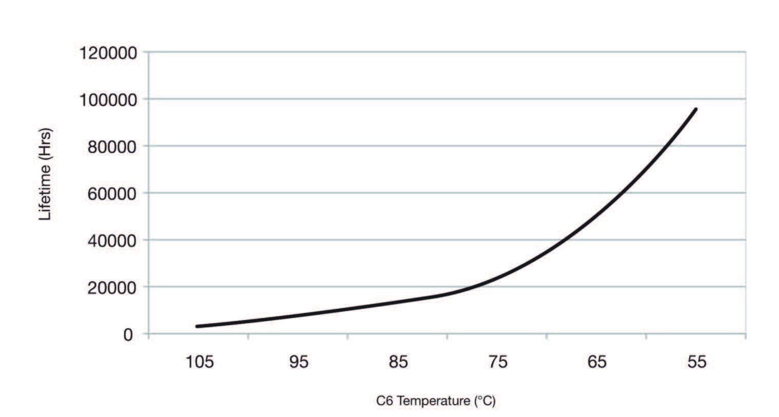
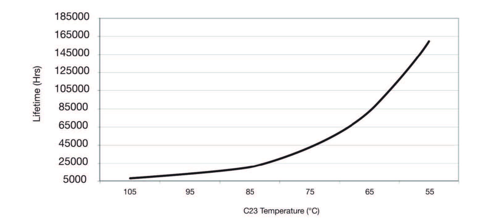
Many power supply data sheets, such as those for XP Power’s GCS series, identify the key components determining the service life of the product. This includes those that need the end equipment to provide external cooling and those designed for convection-cooled applications. This information, along with data about the application operating environment, helps system designers determine power supply service life more accurately in the end application.
Summary
To accurately predict the lifetime of a power supply it is important to assess it in your specific application using the measurement points and data provided by the manufacturer and applying the mission profile for the end equipment based on average temperature and usage per day.
The Essential Guide to Power Supplies - whether you're new to designing-in an AC-DC power supply or DC-DC converters. All the information you'll need in one easy reference guide.

Gary Bocock
Gary is a seasoned electronics engineer and a Member of the Institution of Engineering and Technology (MIET). With over three decades of experience in the power supply industry, he has held design, development, applications and management roles. For over 25 years, Gary has been a key figure at XP Power, where he has held various engineering and management positions, ultimately rising to the role of Technical Director.