Hi-pot testing and relevant standards
Certifying a new product to relevant safety standards is an essential part of any design and development process. But faced with a myriad of standards, sometimes engineers need clarification regarding the nature of the tests appropriate for each standard. This article highlights some of the recent technical support questions received by XP Power concerning hi-pot testing and relevant standards.
High potential (hi-pot) testing of end systems
Typically there are two voltages used to conduct isolation testing; 3 kVAC and 4 kVAC. For IT and industrial equipment, the international safety standard IEC60950-1 applies to AC-DC power supplies. This stipulates that your product must pass an input to output isolation test of 3 kVAC in order to be compliant. The IEC61010 standard applies to test and measurement equipment and also requires the 3 kVAC test.
Medical equipment is covered by standard IEC60601-1. Input to output isolation tests needs to be conducted at the higher voltage of 4 kVAC in order for the design to comply with this standard.

Figure 1: Typical Power Supply Insulation
R – Location of typical reinforced insulation; B – Location of typical basic insulation; O – Location of typical operational insulation.
Confusion can occasionally occur when the actual system hi-pot testing takes place. Typically there will be two different types of test. Design verification (DVT) and safety testing may take place first, followed by production and customer qualification testing.
Misinterpretation of the relevant standard may result in the product being subjected to a hi-pot design verification test to the levels described above. However, the standards state that production hi-pot testing should not exceed 1500 VAC, or its DC rectified equivalent of 2121 VDC, from input to output or input to ground.
The 3 kVAC and 4 kVAC tests are a stress test for the main transformer only. To conduct these tests the main transformer is removed from the power supply and tested as a stand-alone part. If these test voltages are applied to the supply assembly, a failure may be seen, but it's not a failure of the transformer as a protection barrier, but rather a failure of the basic insulation parts that are tied to ground.
A 1500 VAC test checks the two isolation barriers of the equipment, namely input to output and input to ground.
False failures and possibly damage
For the test to be completed, certain conditions must be met so the product will pass. If the conditions are not met then they can cause false failures and possibly damage the power supply. Typically input to ground and output to ground capacitors can be damaged. A failure can also occur in some primary side FETS and any surge protection devices.
A recent call to the XP Power applications team illustrates the issue. One of our fleXPower series units that comply with both the IEC60950-1 and IEC60601-1 standards was being isolation tested from input to output at 4242VDC (the rectified equivalent of 3000VAC).
A breakdown occurred from the input connection to the chassis. This could have been anticipated since the isolation from the barrier strip to the chassis is designed to withstand a maximum of 1500VAC (2121 VDC). Our applications engineer explained the context of this standard and that, in order to ensure that the transformer would meet the 3000VAC test, it should be removed from the supply and tested separately. Alternatively, the unit could be disconnected from its chassis, and its Y capacitors removed whereupon it would pass the test.

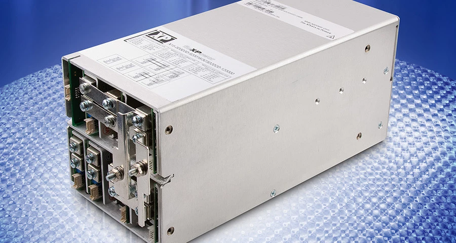
Figure 2: Power supply disassembly may be required for type testing
These test issues are a particular problem in Class I equipment where a protective ground is employed to ensure safe operation. Class II equipment utilizes double or reinforced insulation to ensure safe operation with no provision for protective ground.
Where Class II power supplies are employed the user is able to test from the input to the output of the power supply at 3000 VAC (or 4242 VDC) for ITE devices or 4000 VAC (5656 VDC) for medical devices to verify the insulation in the supply.
Testing a new product
Another good example of the importance of working with a knowledgeable power supply manufacturer is that of a recent issue experienced by one of our customers when taking their product through safety approvals.
Our customer was testing a new product for the monitoring of cell phone networks. The testing had progressed well with the exception of the hi-pot test. This was surprising as the power supply they are using carries medical safety approvals in addition to the ITE approvals that they require, meaning that the isolation specification exceeds the standard in question.
Having verified that the test procedure was correct and that the supply was correctly installed, we got to the question about the test voltage. We found that the voltage applied was in excess of 1500VAC, but not at the 3kV or 4kV level. It was not clear why the higher voltage test was being applied but the test lab were adamant that it was correct.
After further investigation and a joint call with the customer and the test lab to review the test process we quickly concluded that the customer had labelled the product for an input voltage range of 80-264VAC as that is the input range specified for the power supply, they were using. This label led the test lab to base the hi-pot testing on 264VAC rather than 240VAC. Once the label was corrected and the test was re-run at 1500VAC the product passed as expected.
XP, the customer and the test lab were able to work together for a successful outcome and the customer's system is now approved.

Kent Smith
Kent is a Regional Applications Engineer with XP Power covering eastern North America. He's been with XP Power for over 14 years and previously was a design engineer with a company in the test equipment market. Kent graduated with a Mechanical Engineering degree from Rensselaer Polytechnic Institute.