What are the most common mistakes?
Often in the commercial, industrial, medical and military industries, system engineers wait until system qualification before addressing critical functions for EMC and EMI compliance to relevant standards. The most common mistake is the belief that a power supply with EMI compliance certifications to required system standards will ensure system EMI compliance. This is all too often proven to be an incorrect assumption.
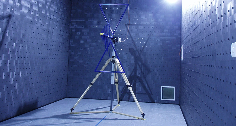
Power supply EMI compliance tests are controlled by the relevant standards for each industry that is targeted. Test methods and setup are controlled by the individual Safety/EMC standards and provide processes and controls to ensure that EMI tests are consistent regardless of the individual application the supply is intended for.
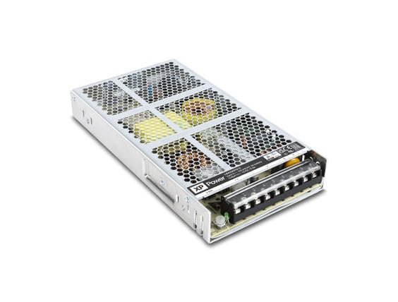
Initial power supply choice is governed by the system requirements. Initially, the system power requirements of output voltage and power drive the power supply choice. Underlying requirements that should be considered are:
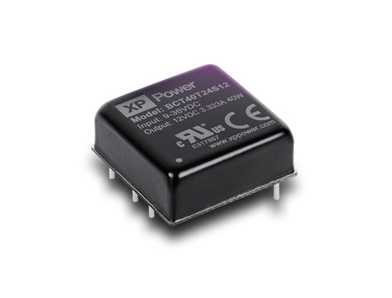
Class I (system Earthed) or Class II (no Earth connection). Class I input with earth ground usage will yield better results as common mode current and voltage are bypassed to earth. For DC-DC converters, a module with a metal case and a connection for a case pin will help reduce radiated emissions when connected to a suitable pcb ground plane but added external filter components for conducted emission reduction will typically be required.
System Earth leakage current (for Medical systems, low patient leakage current and patient touch requirements may be applicable). If low earth leakage current is required, common mode filtering internal to the supply is limited so inductive elements at the system level should be planned for early including a Medical Inlet EMI filters. If standard earth leakage is applicable (3.5mA maximum) at the system level, a supply rated for low earth leakage can be used and modified internally to improve common mode noise rejection should problems arise.
Is Class A or Class B conducted and radiated EMI compliance required? Determine what margin below the limit is required. Many system engineers require 6db margin. Using a Class A compliant supply in a Class B application may require additional filtering (inductive and capacitive) at the system level.
Power supply characteristics
Once the basic power needs are known, other individual power supply characteristics can be evaluated that may impact system EMI compliance:
Input and output connections – these may be installed as part of the supply or may require customer added connections. Cables installed integral to the supply (eg. desktop type) will have been tested during the power supply compliance tests. Cables that are added during system installation are unknown and typically are a source of emissions so particular attention must be paid to cable lengths, proximity to other cables and/or system switching components and logic circuits. Cabling will simulate an antenna and will broadcast noise through out its length. Inductive components placed on long cable runs can mitigate radiated and conducted emissions.
Mounting provisions – desktop type, pcb mount or hard mechanical installation. Hard mechanical mounting provisions are always desirable for Class I input requirements which rely on solid Earth ground to ensure the best common mode noise rejection. For chassis mount and pcb type supplies, use all the provided mounting holes/hardware provided to ensure solid mechanical connections for proper grounding. DC-DC converters mounted to pcb’s will need at least one ground plane in the pcb to separate power from signal traces. If a case pin is provided on the DC-DC module with a metal case, allow provisions on the initial system pcb design for the case pin to be connected or disconnected during initial EMI verification tests.
System switching frequencies if any should be well understood before EMI tests are started. These fundamental frequencies and associated harmonics will show up during initial test plots and should not be confused with the power supply switching frequencies.
Added inlet EMI filters in the system may be required depending on the supply specification for earth leakage current, EMI Class rating and external connections so additional space should be considered early in the design phase.
XP Power provides customer on-site and at test labs with technical assistance during all phases of customer system testing. XP Power also has four facilities with EMI test capabilities to support system level testing for customers.

Gregory Melton
Greg has been in the power industry for over 43 years, joining XP Power in 2008 as a Power Systems and Application Engineering manager in North America.