Issue 6 of Defence Standard 61-5 part 6
In February 2009, the UK Ministry of Defence published issue 6 of Defence Standard 61-5 part 6 to cover 12 and 24V systems. This issue 6 version has a major change when compared to issue 5 which had been originally published in 1990. The main difference is to define how electrical equipment survives when subjected to the DIT08.B load dump.
Load dump occurs when a heavily loaded electrical system exhibits a loose battery terminal, which can be caused by the shock of the military vehicle traversing over rough terrain and the resulting voltage transient presented onto the electrical system by the poor connection defined in the commercial vehicle standard ISO 7637-2.
System design engineers were concerned with the power surges and transients associated with these types of high energy surges, recognising that these were the most difficult to achieve compliance to and had the largest effect on system integration and reliability.
Previously, the highest surge requirement on a 28V system would be when the system ran without the battery connected and was fed from only the alternator. The surge is 80V for a period of 80ms and was the result of an instantaneous change in power demand. The figure below shows both the new load dump and 80V surge from Issue 5:

Surge is a common occurrence
Defence-standard-61-5An 80V surge is a common occurrence on 28V military vehicles and, as such, it is imperative that the electronic equipment continues to operate continuously throughout this surge.
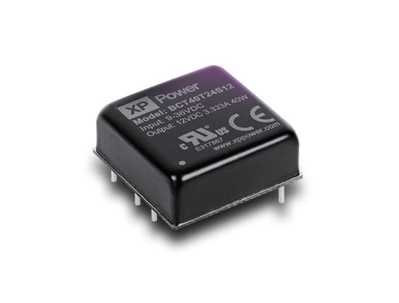
In 28V vehicle applications, there will be a DC-DC converter to lower the input voltage to a more manageable level, such as 3.3V, 5V and 12V, for the electronic circuitry it will be powering. Whereas Issue 5 only concerned itself with 24V systems, issue 6 covers 12 and 24V systems so you need the input range to be 9-36VDC to cope with both voltages.
To protect this converter, an active clamp circuit would be fitted using a MOSFET which, during a surge, becomes resistive. The excessive voltage which is above the input range of the DC-DC will be dropped across the MOSFET and dissipated as heat therefore making sure the input voltage is kept within range.
Too much energy
The problem here is that there is too much energy in the load dump surge and it cannot sensibly be dissipated as heat so something else within the system has to be able to handle it.
In a 28V DC system, the load dump surge is around a factor of 5 times that of the 80V surge. The peak voltage is over 2.5 times the magnitude, 202V surge, meaning that existing surge protection designed for issue 5 in the equipment would be inadequate to cope with the Issue 6 energy levels.
There are a couple of ways to cope with this surge. The first is to recognise that this is a rare occurrence and, if it happens, the system can just turn itself off. This approach is suitable if the system electronics are able to safely shut down and then restart once the surge has passed.
The other is to use energy stored in input capacitors and a wide input range, 9-36V input DC-DC converter. This enables the input to be disconnected during the surge and the system to run from the stored energy with the wide range input of the DC/DC extending the hold-up time available.
In higher power systems, due to the size of the capacitance required, this would normally involve the reduction of the load by removing non-critical elements of the end application.
The energy in the capacitor is stored at the maximum input voltage of 36VDC. Available hold-up time can be calculated from…

where:
T = hold up time
C = Input Capacitance
V1 – 36V
V2 = 9V
P = input power to the DC/DC converter
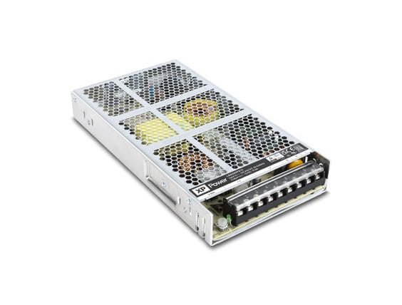
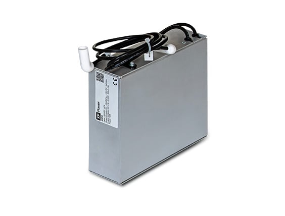
Hold up time can be extended by introducing a hold-up module such as XP’s MTH100 which charges the hold-up capacitance to a higher voltage (50 VDC) to significantly increase the stored energy (by a factor of two) as the stored energy is proportional to the square of the applied voltage.
Standard input surge protection module
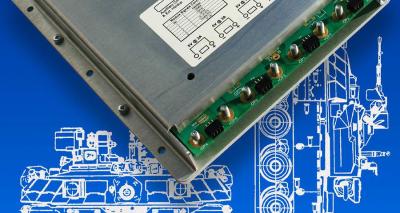
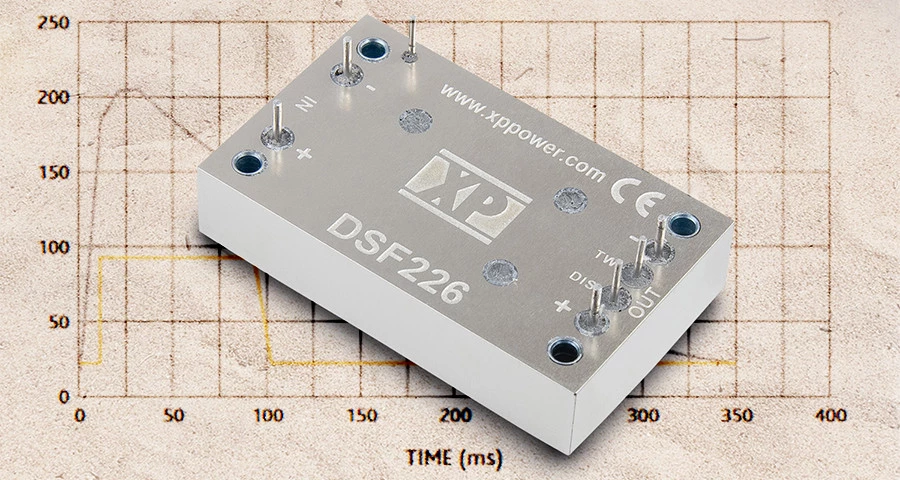
A proven method to achieve compliance for a DC-DC power system is to use a standard input surge protection module such as the DSF226 from XP, which is a surge protection module and EMC filter combined. The DSF226 complies with DEF STAN 61-5 part 6 issue 6 load dump requirements and meets the internationally recognised immunity and emission standards MIL-STD 1275A-D, DEF STAN 59-411 & MIL-STD 461C.
Providing active surge protection, the unit allows for the full output power to be supplied over the entire 15 - 33 VDC, accommodating transients down to 10 VDC for up to 1 s. The output of the module tracks the input voltage and is clamped at < 36 VDC. The DSF226 filter and surge protection module is ideal for use in combination with XP Power's MTC family of military-specification DC/DC converters, QSB and ICH series of power bricks.
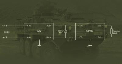
The DSF226 can also be combined with XP Power's J series of 24V 4:1 input converters for multiple output COTS defence applications. See below the simplified schematic diagram: -

Defence-standard-61-5v2XP can also provide engineered solutions integrating the standard modules into a bespoke application-specific assembly or design a custom solution for applications that cannot be fulfilled through our standard product range.
Our Custom Power team provides the support to deliver a power solution tailored to the customer need to achieve DEF-STAN or MIL-STD EMC compliance.

Daniel O'Donnell
Daniel O'Donnell has been working in the power supply industry for over 20 years and throughout this time has had extensive experience in the rail and defence industries designing in XP Power's market leading products