
We tackle 6 of the most common challenges.
Overview
In precision analytical applications like mass spectrometry, devices require accurately specified and designed high voltage power supplies.
- Depending on the application, there are different demands on spectroscopy power supplies – a solution-based approach is needed.
- Deploying multiple power supplies in the same equipment presents extra challenges.
- We share how to solve the most common design problems for high voltage power supplies in mass spectrometry.
1. Ripple reduction beyond the power supply
In mass spectrometry applications, high voltage power supplies are required to deliver high voltage with minimum ripple and noise. In a high voltage DC-DC converter, the ripple frequency is related to the switching frequency of the supply. We specify the frequency of devices in our product datasheets.
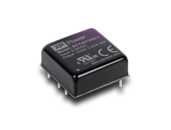
XP Power offers a wide range of miniature high voltage DC-DC converters with low ripple and noise. To further reduce output ripple that’s related to switching frequency, customers can use additional filtering components, such as an RC low pass filter.
This consists of a resistor and a capacitor connected in parallel mode. The RC low pass filter sets a cut-off frequency, allowing signals with a lower frequency to pass through while reducing higher frequency signals.
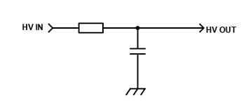
Figure 1: A low pass RC filter
2. Designing an RC low pass filter
First, we determine which frequencies must be filtered out. In the following example, we have selected 120kHz, the switching frequency of high voltage module C80N from XP Power in this circuit setup.
The cut-off frequency should be sufficiently different from the frequency to be filtered to allow for enough damping of the oscillation.
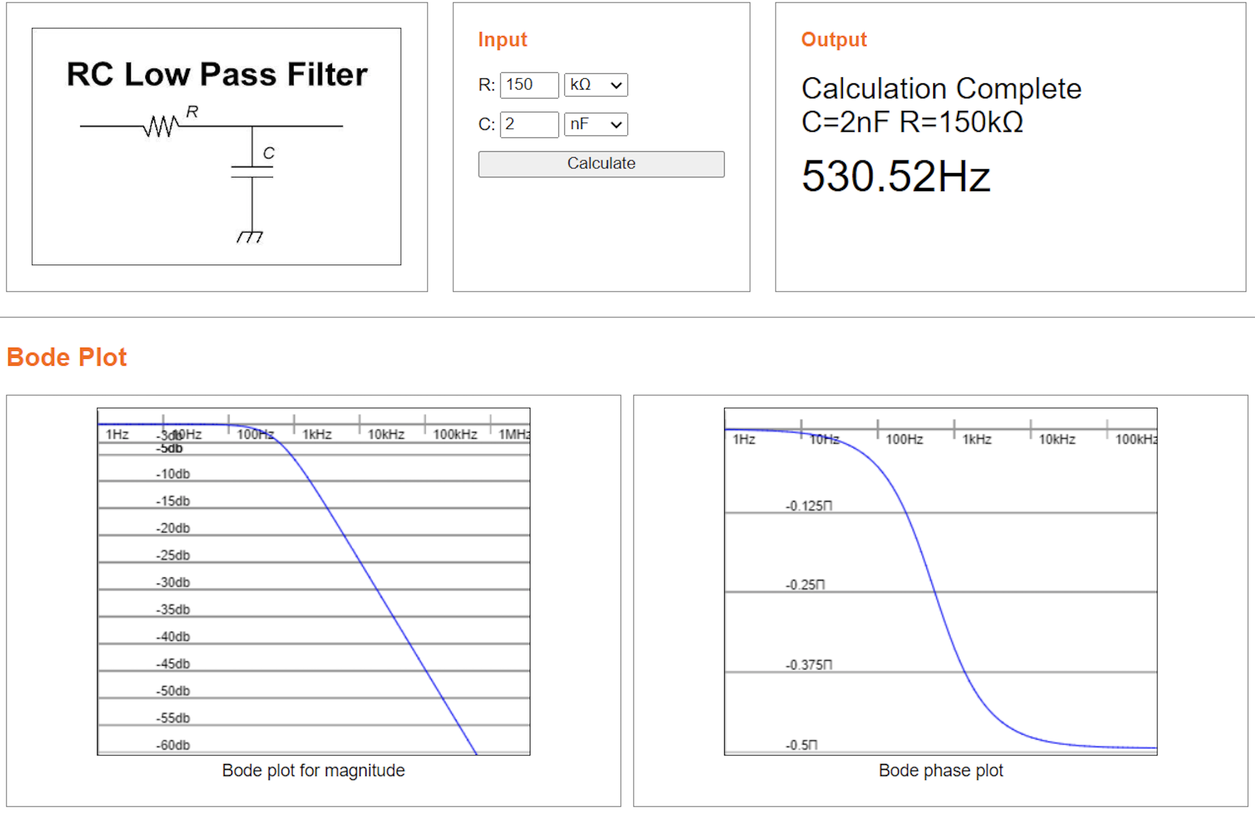
Figure 2: Calculation for a low pass RC filter
We selected a 150kOhm resistor and a 2nF capacitor. The following oscilloscope diagrams show how the ripple and noise levels are reduced significantly.
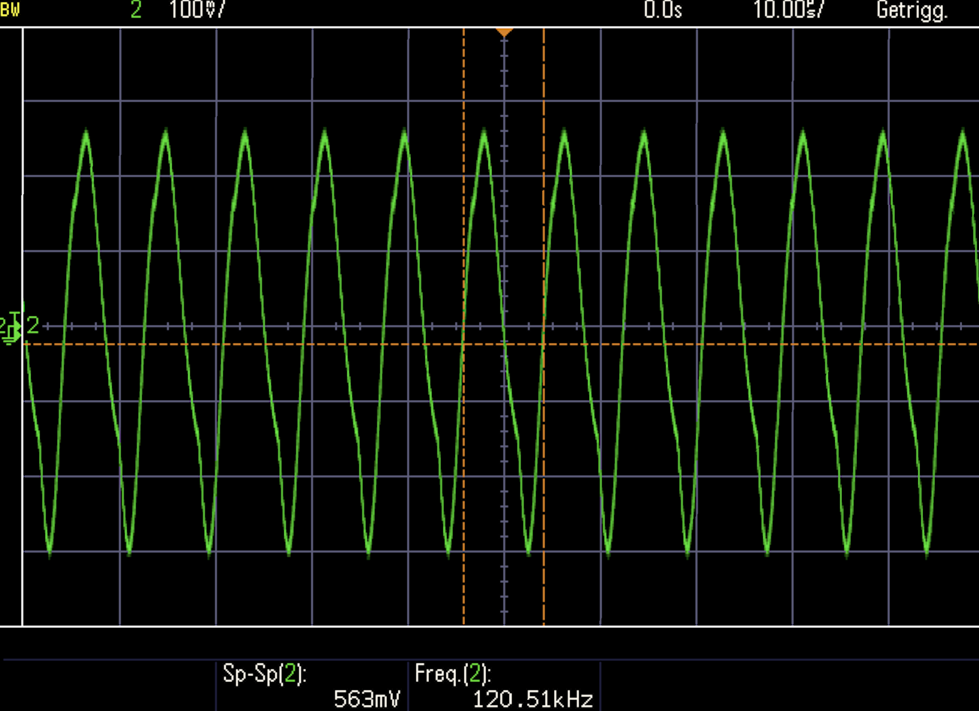
Figure 3. Measurement: without low pass RC filter
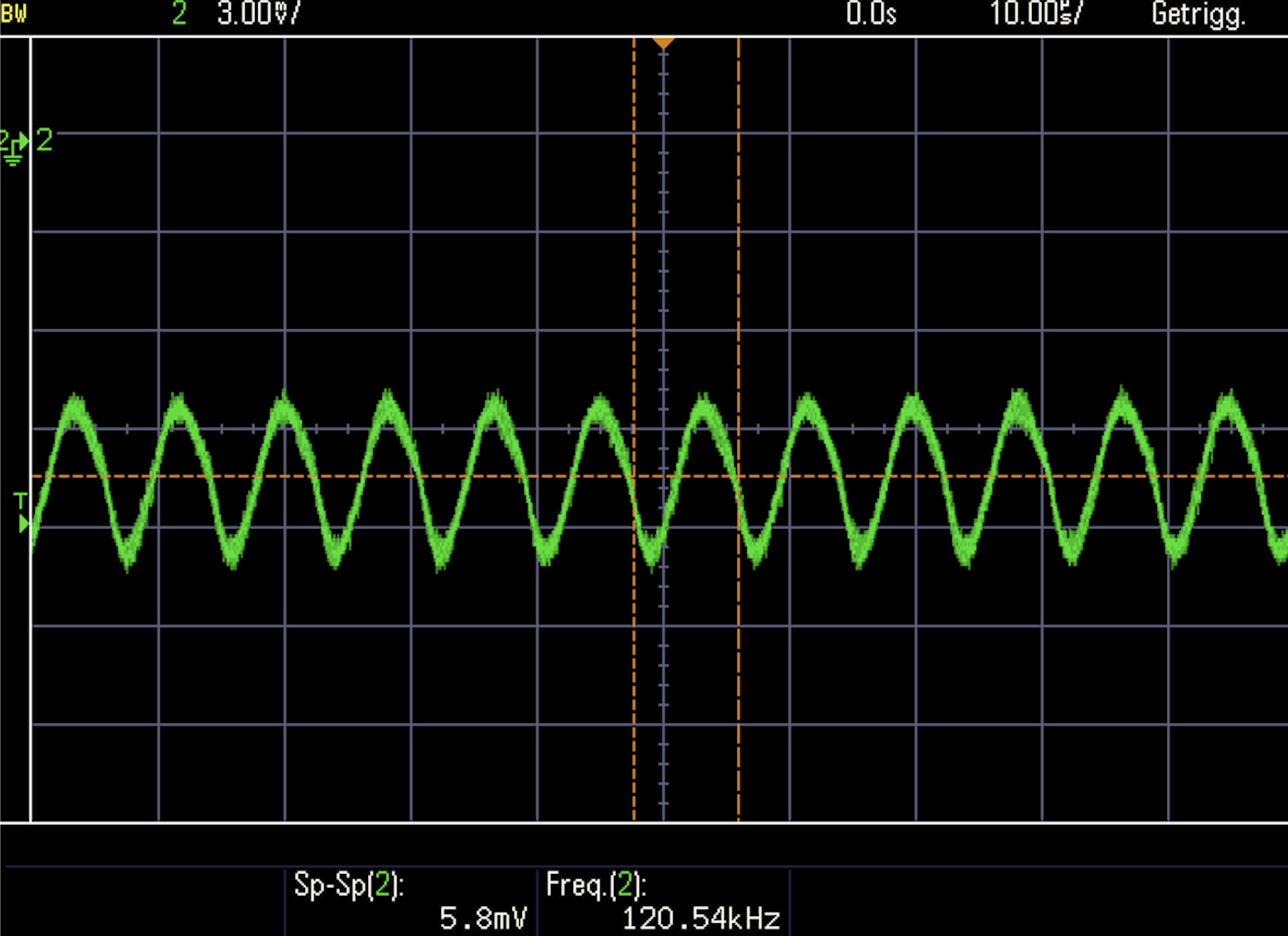
Figure 4. Measurement: with low pass RC filter
3. Setting up cascading high voltage power supplies
High voltage power supplies in mass spectrometry may operate at a different potential from the earth. That means that one power supply "floats" on another’s reference potential.
A detector floating on drift tube potential is an example of this arrangement. The best solution is to use an isolated high voltage power supply, where the Isolation rating of the supplies on higher potential must be at least equal to the floating voltage.
This galvanic isolation is achieved by the transformer and other devices if it is a regulated power supply. The following diagrams show how we can arrange cascading high voltage modules.
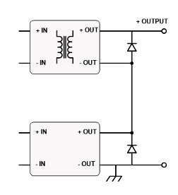
Figure 5: Floating positive high voltage
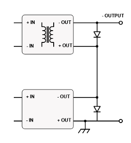
Figure 6: Floating negative high voltage
4. Designing bipolar high voltage power supplies with zero crossing
In electrical ion lenses, there is often a need for bipolar high voltage power supplies. In these electro-optic applications, there can be a requirement to swing from negative to positive high voltage, passing cleanly through zero. The diagram below shows the simplest and most cost-effective way to achieve this.
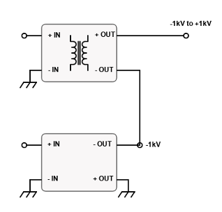
Figure 7: Bipolar high voltage configuration
The output voltage of the first module is set to -1kV. The output of a second module can be referenced to this -1kV. The isolated 2 kV module is set up in cascade over the module and is controlled from 0 to 2 kV.
This module will generate a voltage that can be controlled linearly from -1 kV to +1 kV with no significant non-linearities nor instabilities in the transition from negative to positive.
It’s important not to leave the output section floating with the power on, because the output may electrostatically charge to a voltage more than the isolation rating – this may cause damage.
This approach avoids the expense and space of a typical off-the-shelf bipolar power supply, providing a cost-effective solution for OEM designs.
The diagrams below show how the high voltage is passed in a linear fashion through 0 and each value can be precisely adjusted, even near to zero.
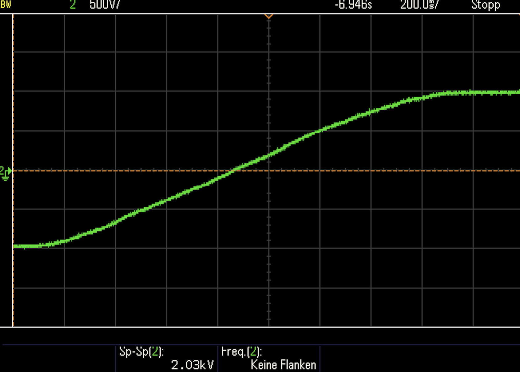
Figure 8. Measurement: +1kV to -1kV linearly through 0
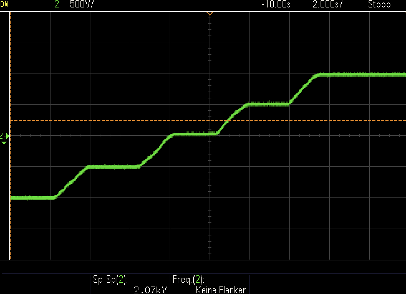
Figure 9. Measurement: output voltages in range +1kV to -1kV
5. Protecting high voltage power supplies against voltage transients
In mass spectrometers, many different electrical potentials may be juxtaposed, so interactions can occur between high voltage power supplies.
We recommend that systems with multiple high voltage power supplies include supplemental protection circuitry for each supply, to protect against fault conditions.
If an arc occurs between two high voltage power supplies with different output voltages but the same polarity, the supply with the lower nominal voltage can be damaged by over-voltage.
The high voltage arc can be a multiple of the nominal voltage of the module with the lower nominal voltage, which can lead to power supply failure. A good solution can be to add a high voltage protection diode at the output of the high voltage power source with the lower nominal voltage.
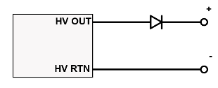
Figure 10: Protection against voltage transients
The diagram above shows how the power supply with the lower output voltage can be protected by a high voltage diode.
The diode should have a reverse breakdown voltage, which is the highest voltage that can arc over to the module. The rated current should be higher than the highest current in the system.
6. Protecting high voltage power supplies from reverse current
When there is an arc between high voltage modules with different polarities, each supply tries to deliver its rated current. This exposes the output to a supply with a higher current of opposite polarity.
The supply with lesser current may be forced to source or sink current beyond its capability, which can lead to overload and damage to the supply.
To avoid the problem, we can use a reverse-biased diode at the high voltage power supply output to return. The diode must be able to carry the current of the high voltage supply that has the opposite polarity.
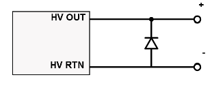
Figure 11: Protection against different polarity
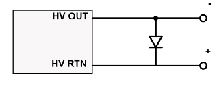
Figure 12: Protection against different polarity
Summary: Accuracy, reliability and additional specific functionalities are the key requirements for high voltage in mass spectrometry. Readily available, cost-effective high voltage DC-DC converters can meet those goals.
XP Power offers a wide range of DC-DC high voltage converters and power supplies designed for precision scientific use in mass spectrometry.

Maik Donix
Maik has spent over 13 years working in the High Voltage industry having initially studied High Voltage Engineering at the Technical University of Dresden. His role at XP Power is an Application Engineer for High Voltage and Radio Frequency products.